Grbl4crp850: Difference between revisions
From
No edit summary |
No edit summary |
||
| Line 26: | Line 26: | ||
=Approaches= | =Approaches= | ||
Verified as of revision 0.3: machine travel in the X, Y, Z, and mirrored axes, in positive and negative directions, as well as homing and endstop sensors. | |||
Enabling additional functions may require some minor modifications. Unused signals have been routed to a breakout header for easy access. | |||
<gallery> | <gallery> | ||
Grbl4crp850r0.2.jpg|revision 0.2 | Grbl4crp850r0.2.jpg|revision 0.2 | ||
Revision as of 09:29, 20 September 2021
Part: Grbl4crp850

| Designers: | Timothy Schmidt |
|---|---|
| Transformations: | Etching, Photopolymer printing, Soldering |
| Tools: | Soldering irons |
| Parts: | Printed circuit boards, Solder, Headers |
| Files: | grbl4crp850.fzz |
| Github: | Replimat |
Introduction
A simple board to control AvidCNC equipment using Free Software.
Challenges
The avid controller requires more pins than grbl provides, so grbl-Mega-5X was used instead.
Approaches
Verified as of revision 0.3: machine travel in the X, Y, Z, and mirrored axes, in positive and negative directions, as well as homing and endstop sensors.
Enabling additional functions may require some minor modifications. Unused signals have been routed to a breakout header for easy access.
-
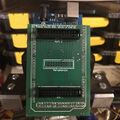
revision 0.2
-
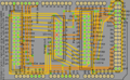
revision 0.3
